Dimension Icon Heater/Cooler Setup
- Verify that the Thermal Applications Controller (TAC) is set to the appropriate voltage configuration for the regional power supply (see Figure 1).
CAUTION: Do not obstruct the ventilation slots of the Thermal Applications Controller.
- Set the TAC power switch to Off.
- Plug the power cord into the rear panel of the TAC and into the power supply.
- Connect one end of the 9-pin connector into the Serial Port on the back of the TAC and the other into one of the COM ports of the computer.
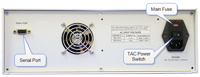
Figure 1: Thermal Applications Controller (Rear Panel)
- Verify that the power disconnect device is readily accessible.
- Set the TAC power switch to On (see Figure 1), and verify that the controller has power.
- Place the Heater/Cooler base against the Dimension Icon chuck base so that the lip overlaps the shelf in the chuck base. See Figure 2.
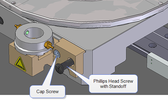
Figure 2: Heater/Cooler attached to the Dimension Icon chuck base.
Although the magnets in the Heater/Cooler base will hold the heater/cooler base, firmly secure the Heater/Cooler base using the supplied cap and Phillips head screws, with a standoff on the Phillips head screw. This standoff will be used to support the Heater/Cooler hoses and cable.
- Using two cap screws, bolt the gas/water manifold to the air table on the left side of the microscope. See Figure 3.
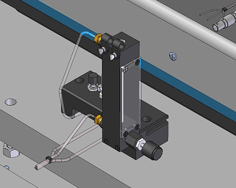
Figure 3: Manifold attached to the air table of the Dimension Icon.
- Plug the 7-pin Lemo connector on the cable from the Heater/Cooler magnetic base into the 7-pin receptacle of the heater extension cable.
- Plug the 7-pin Lemo connector on the heater extension cable into the 7-pin Scanner receptacle on the front panel of the TAC (see Figure 4).
- Connect the tip heater cable to the 4-pin Lemo connector labeled Tip Heater on the front panel of the TAC, shown in Figure 4, and the other end into the 9-pin D-sub connector labeled Heater/Cooler on the top of the Dimension Icon electronics box, shown in Figure 5.
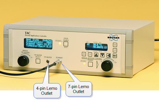
Figure 4: Thermal Applications Controller (Front Panel)
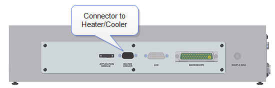
Figure 5: Electronics Box with Heater/Cooler Connector
| www.bruker.com
|
Bruker Corporation |
| www.brukerafmprobes.com
|
112 Robin Hill Rd. |
| nanoscaleworld.bruker-axs.com/nanoscaleworld/
|
Santa Barbara, CA 93117 |
| |
|
| |
Customer Support: (800) 873-9750 |
| |
Copyright 2010, 2011. All Rights Reserved. |
Open topic with navigation